
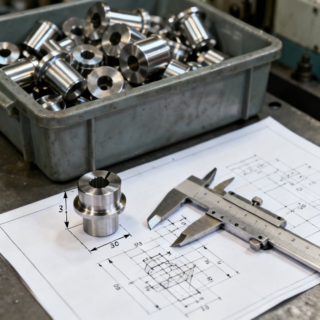
Design With the Machine in Mind
A part drawn without regard to the cam lathe that will make it works perfectly — and costs more than it should. The cam automatic lathe is a beautifully constrained machine: it turns, faces, and cuts off along the axis with fixed tool slides. Respect those constraints and it rewards you with six-second cycles and five-nines quality for production. Ignore them and it hands the work to a CNC cell at three times the price.
Rule 1: Keep Geometry Rotational
Diameters, steps, grooves, chamfers, and forms along the axis are what the cam slides cut well. Anything off-axis — cross-drilled holes, flats, hexes, keyways, angled faces — pushes work into secondary mill-drill operations. Design them into the part only where function requires them, and cluster them so the secondary machine runs them in one setup rather than three.
Rule 2: Use Standard Tool Shapes
The turning stations use standard forming and grooving tools. When the required profile matches an off-the-shelf tool shape, the cam can be cut and the tool ground same-day. When it demands a custom ground form, the cam jobs get a longer lead — a cost that lands squarely in the quote. Design bends, radii, and grooves to map to standard tools wherever possible.
Rule 3: Chamfer and Break Every Edge
The cam sequence cuts faster and cleaner when every sharp transition is chamfered or broken. Zero-degree edges leave microscopic burrs that complicate handling, cause misalignment in assembly, and eat into inspection consistency. A 0.3–0.5 mm break is cheap to cut, prevents slicing operators' fingers, and keeps parts feeding automatically through assembly without snagging.
Rule 4: Choose a Sensible Stock Size
Cam lathes feed continuous bar stock — usually 12 mm or 13 mm rounds, 1/8, 5/32, or other standard diameters. When the part's largest diameter lands far below a standard bar, you are paying for the extra material to be turned away. Draw the part so its diameter matches a common stock size, not a number in between.
Rule 5: Be Realistic About Tolerances
Cam lathes hold dimensions well — typically to ±0.02–0.05 mm on diameters and lengths with quality tooling and good machine condition — but they do not hold the field against CNC on number: tolerance creep happens with tool wear. The design's duty is to reserve tight tolerances for the features that genuinely need them: bearing zones, seal journal, press fits, thread-run. Where a wider tolerance serves, leave it to default rather than tightening unnecessarily.
Rule 6: Short Parts Beat Long Parts
Length is cost in the world of the small automatic lathe: a 2 mm long part is a fast, high-yield job; a 60 mm one adds cycle time, invites deflection, and reduces the number of stations that can cut simultaneously. Where function allows a shorter lever or stacked design, that is the design that builds fastest.
Quick Reference: Typical Cam Lathe Tolerances
| Feature | Realistic Tolerance |
|---|---|
| Diameters | ±0.02–0.05 mm |
| Lengths | ±0.03–0.08 mm |
| Concentricity | 0.01–0.03 mm TIR on standard work |
| Surface finish | Ra 0.8–3.2 µm |
| Break edges | 0.2–0.5 mm standard |
Bring the Part Early
Every design rule above is easier to honor before the drawing is released. Hold-Tech designs and supplies small high-volume turned parts — and reviews drawings for cam lathe compatibility before committing to tooling. Send your part concept or drawing to operator@hold-tech.cn or call +86-186-60386138 and we will tell you what the process can do best.