Design for Manufacturability (DFM): Optimizing Your Parts for CNC Machining and Sheet Metal Fabrication
By the Engineering Team at Hold-Tech Precision Industrial | Published May 9, 2026

Introduction: Why DFM Matters More Than Ever
In today's competitive manufacturing landscape, the difference between a profitable product and a costly mistake is often determined long before the first chip is cut. Design for Manufacturability (DFM) is the engineering practice of designing products with their production process in mind from the very beginning. When applied correctly, DFM reduces manufacturing costs, shortens lead times, improves quality, and eliminates costly design revisions downstream.
For engineers and sourcing professionals working with contract manufacturers in China, understanding DFM is not just a technical advantage—it is a strategic necessity. This comprehensive guide explores core DFM principles tailored for two of the most widely used manufacturing processes: CNC machining and sheet metal fabrication.
What Is Design for Manufacturability (DFM)?
DFM is a systematic approach to product design that optimizes the relationship between design features and manufacturing constraints. The fundamental goal is to produce high-quality parts at the lowest possible cost within the shortest feasible lead time, without compromising functional requirements.
At its core, DFM asks three critical questions:
- Can this part be made efficiently? — Does the design leverage the strengths of the chosen manufacturing process?
- Can costs be reduced without sacrificing function? — Are there features that add manufacturing complexity without adding customer value?
- Is the design robust against process variation? — Will the part function correctly even with normal manufacturing tolerances?
DFM for CNC Machining
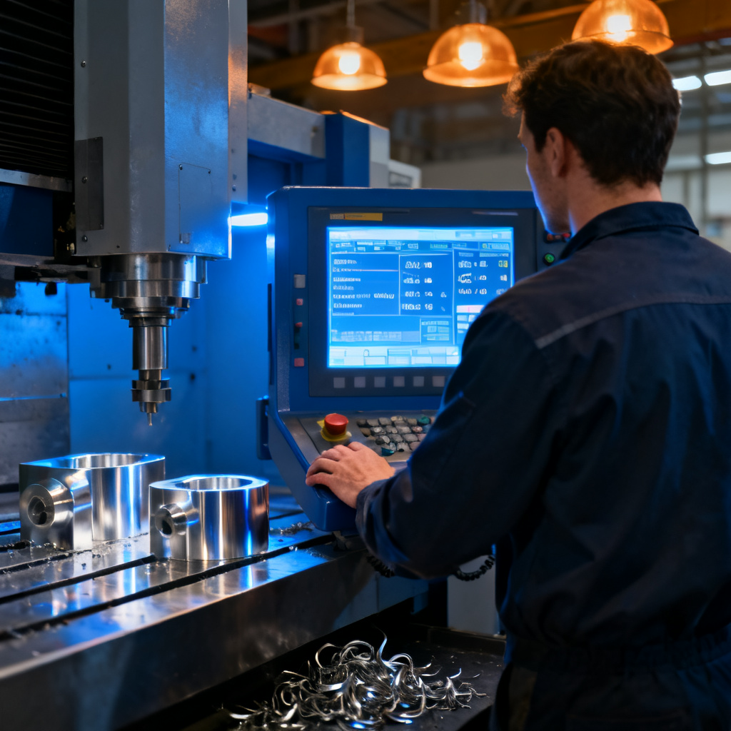
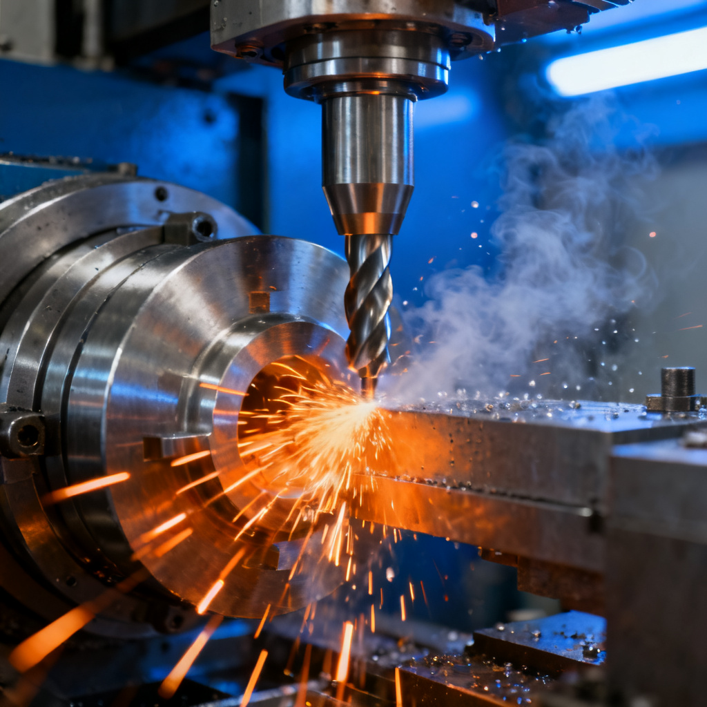
CNC machining is a subtractive manufacturing process that removes material from a solid block (or billet) to create a desired geometry. While extremely versatile, it comes with specific design constraints that, when respected, dramatically reduce cycle times and tooling costs.

1. Avoid Deep Pockets with Small Corner Radii
Cutting tools have a cylindrical shape, which means they cannot cut internal square corners. The smaller the corner radius, the smaller the tool required, and the more passes needed to clear material. A general rule of thumb: design internal corner radii to be at least 30–50% of the pocket depth. For example, a 10 mm deep pocket should have a minimum corner radius of 3–5 mm. This allows the use of larger, more rigid tools that cut faster and last longer.
2. Minimize Deep, Narrow Cavities
Deep cavities with high aspect ratios (depth-to-diameter > 3:1) require specialized long-reach tools that are prone to deflection, chatter, and breakage. Whenever possible, design features with depth-to-diameter ratios under 3:1. If deeper features are unavoidable, consider designing the part as two separate components that can be joined—the assembly cost is often lower than the machining cost of a single deep-cavity part.
3. Specify Tolerances Strategically
One of the most common—and costly—DFM mistakes is over-tolerancing. Tighter tolerances require slower feed rates, additional setups, and sometimes specialized inspection equipment. A standard machining tolerance of ±0.125 mm (±0.005 in) is sufficient for most engineering applications without functional fit requirements. Reserve tighter tolerances (±0.025 mm or ±0.001 in) only for critical mating surfaces and bearing seats. According to industry benchmarks, tightening a tolerance from ±0.125 mm to ±0.025 mm can increase machining cost by 50–100%.
4. Design for Standard Tool Sizes
Standard end mill diameters (e.g., 3 mm, 6 mm, 10 mm, 12 mm, 16 mm, 20 mm) are readily available and significantly less expensive than custom sizes. Designing features such as slots, radii, and holes around standard tool dimensions eliminates the need for custom ground tools and reduces machine setup time. At Hold-Tech Precision Industrial, our engineering team routinely reviews customer designs to recommend tooling optimizations that reduce cycle times without compromising design intent.
5. Avoid Thin Walls
Thin wall sections are prone to vibration during machining, leading to poor surface finish and dimensional inaccuracy. For metal parts, a minimum wall thickness of 0.8–1.5 mm (depending on material) is recommended for small features, and 3–5 mm for larger structural sections. Aluminum and brass are more forgiving, while titanium and stainless steel require thicker walls due to higher cutting forces.
DFM for Sheet Metal Fabrication
Sheet metal fabrication encompasses cutting, bending, forming, and joining operations. DFM principles for sheet metal focus on bend geometry, material utilization, and tool access.

1. Maintain Consistent Bend Radii
Whenever possible, specify a single bend radius across the entire part. Changing bend radii requires tool changes on the press brake, adding setup time. The recommended inside bend radius is equal to the material thickness (1× T) for most steels and aluminum alloys. Using a consistent radius also simplifies quality inspection—Hold-Tech's quality control team can verify parts faster when bend parameters are standardized.
2. Leave Sufficient Flange Length
The flange height must be sufficient to engage the press brake tooling. A general guideline: minimum flange length should be at least 4× the material thickness plus the bend radius. For example, for 2 mm thick steel with a 2 mm bend radius, the minimum flange height is 4 × 2 + 2 = 10 mm. Shorter flanges require special tooling and may result in inconsistent bends.
3. Place Holes and Cutouts Away from Bend Lines
Holes and cutouts located too close to a bend line can become deformed during bending. Industry best practice is to maintain a minimum distance of at least 2.5× the material thickness plus the bend radius from the edge of the hole to the bend line. For a 2 mm thick part with a 2 mm bend radius, holes should be at least 2.5 × 2 + 2 = 7 mm from the bend. When this guideline is violated, parts often require secondary operations such as drilling after bending, adding cost and cycle time.
4. Design for Standard Sheet Sizes
Raw sheet metal comes in standard sizes (typically 4×8 ft or 5×10 ft). Nesting parts efficiently on a standard sheet minimizes scrap and reduces material cost. Rectangular parts with simple geometries are easiest to nest. Irregular shapes and parts with sharp angles increase scrap percentage. Hold-Tech Precision Industrial offers free DFM analysis for sheet metal designs and can suggest geometry adjustments that improve material yield by 15–25%.
5. Avoid Hems in High-Stress Applications
Hems (folded edges) add stiffness and remove sharp edges, but they are difficult to form consistently in high-strength materials and can introduce stress concentrations. For structural applications, consider a formed joggle or a separate edge trim instead of a hem. If a hem is necessary, specify an open hem (45–90 degrees) rather than a closed hem (180 degrees) to reduce forming force.
The Holistic DFM Process

Effective DFM is not a checklist—it is a collaborative process. The best results emerge when design engineers and manufacturing experts communicate early and often. Here is the DFM workflow we recommend:
- Concept Review: At the concept stage, identify the primary manufacturing process and approximate material. This determines the DFM rules that apply.
- Design Guidelines: Apply process-specific DFM rules during detailed design. Reference the guidelines above for CNC machining and sheet metal.
- Manufacturing Feedback: Share preliminary designs with your manufacturing partner. At Hold-Tech Precision Industrial, our application engineers review every new design and provide a free DFM report highlighting cost reduction opportunities, tolerance concerns, and cycle time estimates before production begins.
- Prototype Validation: Produce prototype quantities to validate the design and manufacturing assumptions. This step catches issues that CAD analysis cannot predict.
- Production Ramp: Use validated DFM parameters for full-scale production. Monitor quality data to identify further optimization opportunities.
Common DFM Mistakes and How to Avoid Them
| Mistake | Impact | Solution |
|---|---|---|
| Over-specifying surface finish | Increases cycle time 20–40% | Specify Ra 1.6 µm as default; reserve Ra 0.4 µm for sealing or bearing surfaces only |
| Designing sharp internal corners | Requires EDM or special tooling | Add corner radii of 1–3 mm (CNC) or redesign as laser-cut tab (sheet metal) |
| Undercuts without tool access | Adds 5–10× to machining cost | Redesign as assembly or use standard lollipop cutter sizes |
| Uneven wall thickness | Causes distortion and warpage | Maintain uniform walls within 20% variation |
Case Study: How DFM Saved 30% on a Complex Bracket Assembly
A recent collaboration between a European automation equipment manufacturer and Hold-Tech Precision Industrial illustrates the real-world impact of DFM. The original design for a mounting bracket assembly consisted of seven CNC-machined components with tight tolerances across all mating surfaces. Total quoted cost from multiple suppliers was approximately $4,200 per assembly.
The Hold-Tech engineering team proposed a DFM redesign that reduced the assembly to four components: two CNC-machined parts and two laser-cut and formed sheet metal brackets. Key changes included:
- Consolidating three machined brackets into one sheet metal bracket with formed flanges
- Relaxing tolerances on non-critical mounting holes from ±0.05 mm to ±0.2 mm
- Replacing threaded inserts with formed and tapped holes in the sheet metal components
- Standardizing corner radii across all machined features to allow common tooling
The result: per-unit cost dropped to $2,850—a 32% savings—while assembly time decreased by 40% due to fewer parts. Lead time was reduced from 6 weeks to 3 weeks, and the customer reported zero non-conformances in the first production run of 500 units.
Conclusion: Partner with Engineers Who Understand DFM
Design for Manufacturability is one of the highest-leverage activities in product development. Investing time in DFM analysis during the design phase can reduce production costs by 20–40%, shorten lead times, and improve part quality—all while maintaining design intent and functional performance.
Whether you are designing precision CNC-machined components, complex sheet metal enclosures, or multi-process assemblies, partnering with a manufacturing team that provides expert DFM feedback is critical. Hold-Tech Precision Industrial combines deep manufacturing expertise with responsive engineering support, helping customers in Europe, North America, and across Asia bring better products to market faster.
Contact our engineering team today for a free DFM review of your next project:
- Email: [email protected]
- Phone: +86-186-60386138
- Website: https://hold-tech.cn